R & D / production / sales / after-sales one-stop service


More customers update their needs, which is the power source of our development
Advanced technology and excellent team are our advantages
First class products and perfect services are our goal
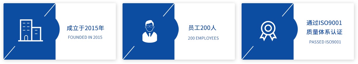
Founded in 2001, Shenzhen Lanfeng Technology Co., Ltd. is located in Building D, fuxinlin Industrial Park, Hangcheng Industrial Zone, Xixiang street, Bao'an District, Shenzhen. It has more than 200 employees, including 5 senior engineers, 6 senior management personnel, and more than 30 sales personnel. It has passed ISO9001 quality system certification and is a professional manufacturer integrating R & D, production and sales. After more than ten years of development, with the strong support of people from all walks of life and the hard work of all employees, Lanfeng technology has developed into one of the world's top five professional infrared receiver manufacturers, with products exported to dozens of countries and regions...