R & D / production / sales / after-sales one-stop service


At present, 850nm and 940nm are widely used in the market, because 850nm has high emission power and long irradiation distance, so it is mainly used in infrared monitoring equipment, while 940nm is mainly used in the infrared remote control of household appliances. Let's learn:
Infrared emission tubes generally have the following categories:
According to the peak wavelength: 850nm, 870nm, 880nm, 940nm, 980nm
In terms of power: 850nm > 880nm > 940nm
In terms of price: 850nm > 880nm > 940nm
At present, 850nm and 940nm are widely used in the market, because 850nm has high emission power and long irradiation distance, so it is mainly used in infrared monitoring equipment, while 940nm is mainly used in the infrared remote control of household appliances.
Peak wavelength: λ P (unit: nm)
The wavelength corresponding to the peak position of the energy distribution measured by the light emitting body or object on the spectrometer is called peak wavelength λ P radiation intensity: power (unit: MW / Sr) is used to represent the infrared energy radiated by the infrared light emitting diode (IR LED).
The radiation intensity (power) is directly proportional to the input current (if), and the emission distance is directly proportional to the radiation intensity (power). MW / Sr: a unit of infrared radiation intensity, which is the amount of light power radiated by the unit solid angle (SR) of infrared light emitted by the transmitting tube
Half power angle: 2 θ 1 / 2 refers to the half power angle when the infrared intensity radiated from the upper, lower or left and right sides of the emission tube is 50% of the maximum radiation intensity of the component.
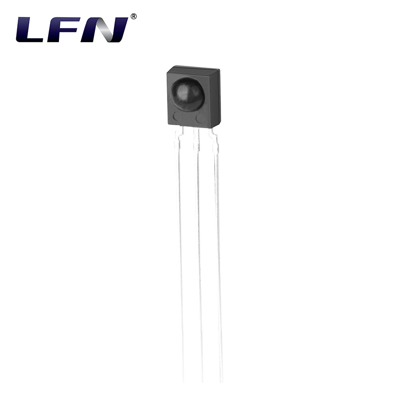
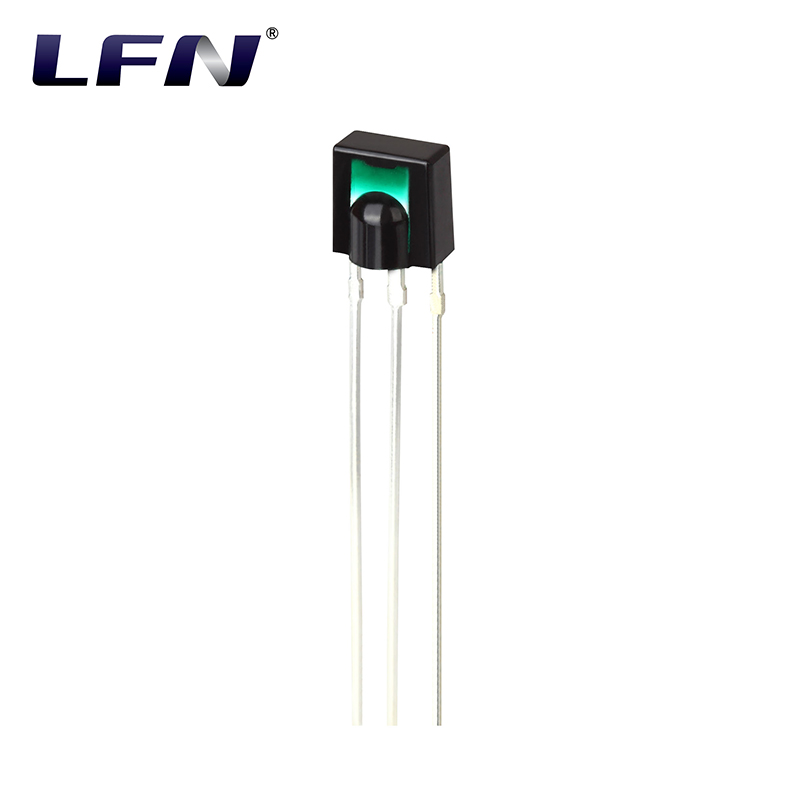
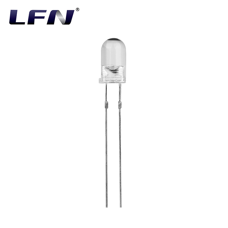
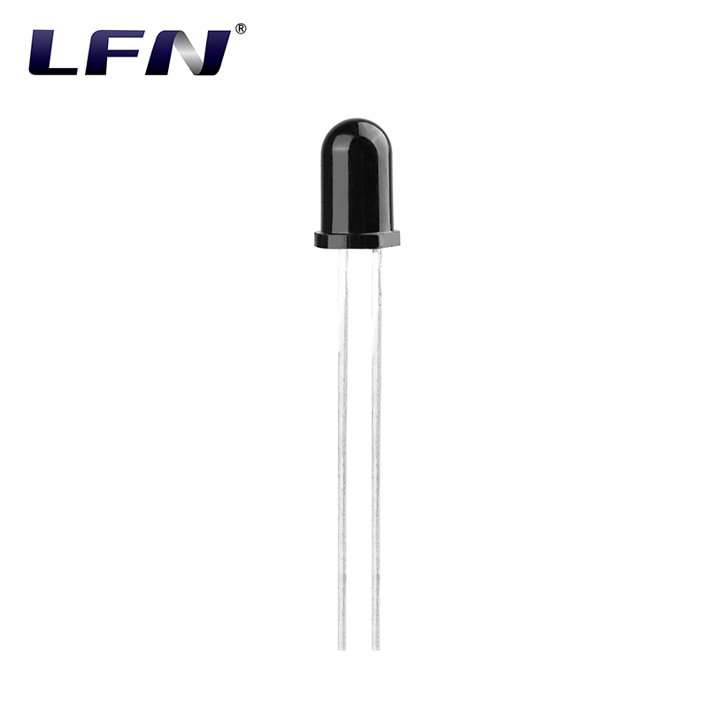
People are used to call the infrared emitting tube and the infrared receiving tube infrared antitube. The shape of the IR pair is similar to that of the ordinary round led. It is difficult to distinguish the transmitting tube from the receiving tube for the first contact. This paper introduces three simple recognition methods.
1. Identification according to internal structure
The internal structure of the infrared counter tube is shown in (a) and (b) on the left. The figure (a) on the left shows an infrared emission tube with a concave core, similar to the shape of a condenser. The left picture (b) is an infrared receiving tube, and the platform in the center of the tube core is provided with an infrared sensitive electrode. The two pins of the infrared pair are 1 long and 1 short, and the long pin is the positive pole, which is the same as the common LED.
2. Measure and identify with a three meter
Use 1K Ω resistance block of 500 type or other type pointer type three-way meter to measure the pole to pole resistance of infrared tube to distinguish infrared tube. Criterion 1: under the condition that the end of the infrared counter tube is not exposed to light, when the probe is changed down for measurement, the positive resistance of the emitter tube is small and the reverse resistance is large, and when the black probe is connected to the positive pole (long pin), the one with small resistance (1K Ω ~ 20K Ω) is the emitter tube. Both the positive and negative resistances are very large. Criterion 2: when the black probe is connected to the negative pole (short pin), the transmitter tube has a large resistance, and when the pointer of the three meter changes with the light intensity, the receiver tube has a swinging pointer.
Note: 1) measure the positive resistance when the black probe is connected to the positive electrode and the red probe is connected to the negative electrode.
2) High resistance means that the pointer of the three meter is basically fixed.
3. For power on test method, a LED and a resistance are connected in series with the tested pair of tubes, as shown in Figure 2 above. The resistance in the figure acts as current limiting, and the resistance value is 220 Ω ~ 510 Ω. LED is used to display the working state of the infrared tube. Use the remote control (TV remote control, etc.) to press any key of the remote control on the tested tube. When the LED is on, the tested tube is an infrared receiving tube. If it's not bright, it's an infrared emitter.